Knowledge · Guides
CNC Machining Guide
A practical guide for buyers and engineers: how the process works, how to choose a machining route for your part, and what to prepare before requesting a quote.
Start here
Four paths through this CNC machining guide
Most questions about machined parts fall into one of four areas. Pick the path that matches where you are now — each card leads to the detailed page for that topic.
01 — Process
Choose a machining process
Milling and turning cover the majority of machined parts. Learn how each removes material, and which fits your part geometry.
02 — Material
Select a material
Machinability, dimensional stability and cost start with the material family and grade — not with the machine.
03 — Quality
Set quality requirements
Tolerances and surface finish define what an acceptable part is, and how it will be measured after machining.
04 — Files & purchasing
Prepare files and purchasing
A complete technical package keeps quoting fast, comparable and free of avoidable back-and-forth.
Fundamentals
CNC machining basics
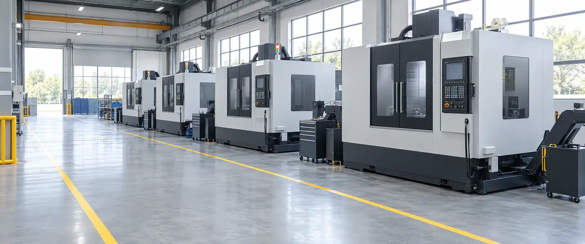
Three questions come up in almost every quote discussion: what is CNC machining, how does CNC machining work, and why do milling and turning cover most parts? This section answers them in the order they affect a purchasing decision: the two machine families that cover most parts come first, followed by the sequence from drawing to finished part.
What is CNC machining?
CNC machining is a subtractive manufacturing process: a computer-controlled cutting tool removes material from a solid workpiece until the part matches its drawing. Because the tool path is defined in a program rather than by hand, the same geometry can be reproduced across a batch with consistent results. Put simply, the CNC machining definition is material removal guided by a program: the drawing sets the requirement, the program sets the path. For the wider background of the technology, see the general reference on numerical control.
How does CNC machining work on the shop floor? A program derived from the drawing drives the machine axes, and the tool follows that path in controlled passes until the part matches the model. The same CNC machining process scales from a one-off prototype to a production batch — which is why the drawing, not the batch size, decides most of the planning.
Milling and turning: the two core families
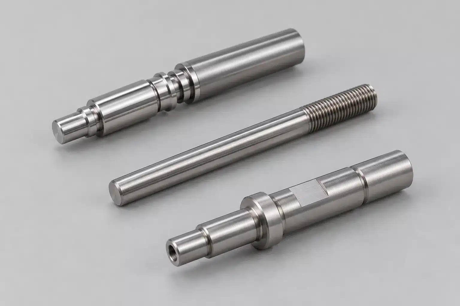
Most machined parts are produced on one of two machine families. In milling, the cutting tool rotates while the workpiece stays clamped to a table — the natural fit for flats, shoulders, pockets, slots and sculpted surfaces. In turning, the workpiece rotates against a single-point tool — efficient for cylindrical features such as shafts, bores and threads. Many parts use both, for example a turned blank with milled flats; the milling vs turning comparison walks through how to decide.
From drawing to finished part
- Review. The print and 3D model are checked for completeness and manufacturability before anything is cut.
- Program and set up. Tool paths, workholding and the measuring strategy for critical features are prepared.
- Machine. Material is removed in controlled passes, with in-process checks on the features that matter most.
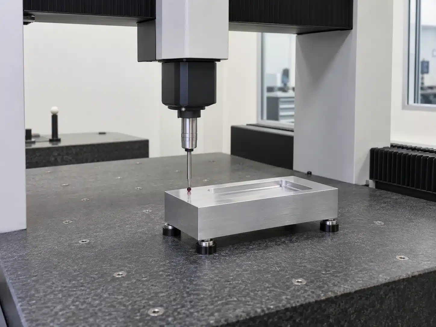
- Inspect. Final dimensions and surface finish are verified against the drawing before the part moves on.
This is the same sequence used when parts are produced as a service — see custom CNC machining services for how that scope is organized.
How material choice shapes the route
Material decisions start with two families, not with a grade. Metals generally carry load, hold threads and resist wear; engineering plastics reduce weight, resist chemicals, insulate electrically and serve as low-friction contact surfaces. The grade refines the choice, but the family already sets the direction.
Four factors decide how a material behaves once it is cut. Hardness drives tool wear and cutting speed. Toughness changes how the part deflects under clamping and cutting force. Thermal conductivity decides how quickly heat leaves the cut zone, which affects both tool life and dimensional stability. Chip behavior controls whether chips clear cleanly or tangle around the tool.
Your drawing should state the material specification, its condition or temper, any heat treatment, and the required surface condition. A trade name on its own is usually not enough to quote from. Compare material families and grades, or go straight to aluminum parts and stainless steel work.
Some material choices need review before quoting. That covers an unusual grade, a heat treatment scheduled between operations, or a plastic that may move after cutting. A surface requirement that constrains the base material belongs in the same group. For polymers the decision often turns on the service environment rather than the drawing — see acetal against nylon.
Decision path
From part feature to process route
Work down the rows rather than jumping to a conclusion. Each row narrows the route from a part feature to a workable plan, and each one assumes the answers above it. Stop where the remaining question depends on your drawing instead of on general guidance — that is the point to send it for review.
This is a judgment order, not a fixed rule. Features, material and quantity interact, and a later row can overturn an earlier answer. Where your part can be read two ways, the drawing and a supplier review decide.
Decision guide
Choosing the right machining approach
Choosing a CNC machining process usually starts with part geometry. Use the table as a first filter, then confirm the details on the linked page.
| If your part is… | Start with | Why |
|---|---|---|
| Prismatic — blocks, plates, housings with pockets | CNC milling | Rotating multi-edge tools cut flats, shoulders, pockets and contours from solid stock. |
| Rotationally symmetric — shafts, bushings, fittings | CNC turning | The workpiece spins against a single-point tool, which suits round features and threads. |
| Mixed geometry — round and prismatic features combined | Milling + turning | Production is planned around the feature that dominates the drawing, often across two setups. |
| Tight tolerances on critical features | Machining tolerances | Tolerance callouts decide which features are held tight — and how they are measured. |
| Cosmetic or functional surface requirements | Surface roughness | Ra / Rz values drive tooling choices, finishing passes and inspection method. |
| Engineering plastics — acetal, POM, nylon | Delrin vs nylon | Grade selection changes machinability, dimensional stability and cost. |
| Prototypes and small batches | Low-volume CNC machining | Setup and inspection economics differ from high-volume production planning. |
Two worked routes, step by step
A stepped bushing. A stainless steel bushing with a stepped outside diameter, a through bore and a thread is built in six steps.
- Read the drawing and separate functional features from clearance features.
- Confirm the material and the critical dimensions before choosing anything.
- Choose turning, because the governing features are round.
- Decide the datum and how the part is held through each operation.
- Confirm the inspection requirements for the features marked as critical.
- Assemble the quote inputs: quantity, material, tolerances, finish, documentation.
A bracket. The same six steps run to a different answer. The governing features are flat faces, pocket walls and hole patterns, so milling leads. A single round boss would add a second operation rather than change the primary route. Material and finish then decide the setup count and the inspection plan.
Run the same six questions on any drawing. The route falls out of the answers, and the questions you cannot answer are the ones to raise at review.
When the surface requirement is the deciding factor, the CNC surface finish guide covers the common finish levels and how they are produced.
Before you request a quote
Preparing drawings and quality requirements
Quoting is fastest when the technical package answers the questions a machinist would ask before cutting metal.
What to confirm before quoting or review
A quote is only as good as the input behind it. Each item below changes how your part is planned, so a gap usually turns into a question before pricing.
- 3D model and 2D drawing. The model carries geometry; the drawing carries dimensions, tolerances and notes. Send both, at the same revision, with units stated. If the two disagree, say which one governs.
- Material specification and condition. State the material, grade and condition or temper. Any heat treatment scheduled between operations belongs on the drawing, not in a later email.
- Critical dimensions and datums. Mark which features carry function and which datum they are measured from. Without a datum scheme, results cannot be compared part to part.
- Tolerances and fits. Hold the features that matter and let the rest sit at general tolerance. Mating parts need the fit stated as a fit, not as two unlinked numbers.
- Surface and appearance requirements. Give the finish per surface where they differ, and separate functional finish from cosmetic appearance. Masking expectations belong here too.
- Inspection and documentation. Say what must be measured and recorded. If you need a report, define its scope before production starts.
- Quantity and delivery. Give the quantity, the expected repeat demand and any schedule constraint. Batch size changes setup planning; a fixed date changes the operation sequence.
What can go straight to quoting
A complete drawing with clear requirements can be quoted directly. Expect an engineering review first when a critical feature needs an unusual setup. The same applies when a tolerance is tight relative to the feature, or the grade is hard to source. Expect a clarification first when model and drawing conflict, units or revision are unclear, or inspection requirements are undefined. None of these is a rejection — they mark where someone has to look at your part before a number means anything.
For the detail behind each input, see how tolerance callouts are interpreted and what a finish value means on a drawing. Two more pages cover how inspection requirements are handled and which file formats to submit. Files are handled under confidentiality terms, and related reading sits in the resource library.
Cost and lead time
What moves cost and lead time
Six factors explain most of the variation between quotes for similar parts.
Geometry
Deep pockets, thin walls and features the tool cannot reach add setups, special cutters and machining time.
Material
Harder or tougher stock cuts more slowly and wears tooling faster.
Tolerance and finish
Tight limits and fine finishes add passes, extra checks and sometimes a second operation.
Quantity
Setup cost spreads across the batch: small runs carry more per part, larger runs amortize planning and inspection.
Inspection and documentation
Reports, traceability and defined acceptance criteria add work after the part is cut.
Manufacturability
A relaxed tolerance or a simplified feature that still meets function can cut both cost and risk.
Schedule follows the same logic: operations needing special tooling or outside processing stretch the timeline, and inspection adds time after cutting. More detail on the factors behind part pricing and on planning small and prototype runs sits elsewhere on the site. Any figure depends on your drawing — a price is only valid after drawing review.
Common questions
Frequently asked questions
Which questions does this guide answer, and which need a service page or an engineering review?
This page covers understanding and selection. It explains what the process does, how your part features point to a route, and what to prepare before asking for a price. Questions tied to one route, material or finish belong on the matching service page. Anything that depends on your drawing needs a drawing review. That covers whether a feature can be produced as drawn, which tolerance is realistic, and what must be inspected.
Can CNC machining produce just one part?
Yes. Because machining does not need a part-specific mold, single pieces and small batches are practical. At low quantities, setup and inspection still shape the timeline and cost — see low-volume CNC machining.
What is precision machining — and is it the same as CNC machining?
Not exactly. Precision machining describes machining work that is held to tight tolerances; CNC machining is the computer-controlled method normally used to achieve them. What decides the result is the tolerance on the drawing, the process plan and the inspection method — not the label. Practical selection criteria for that decision are collected on this page and in the linked guides.
CNC machining or 3D printing — which fits my part?
It depends on material, tolerance, quantity and surface requirements. Machining suits engineering materials and tight dimensional control; printing suits certain low-stress geometries and fast iterations. The CNC machining vs 3D printing comparison walks through the trade-offs.
What drives the cost of a machined part?
Material, geometry complexity, tolerance and finish requirements, quantity and schedule. The CNC machining cost overview explains how each factor moves the price.
What about thin walls or parts that are hard to hold?
These are workholding problems: how a part is supported and clamped decides whether it can be cut accurately without distortion. Common strategies are summarized under CNC workholding.
Review a process — or send a drawing
OREVANTA supports global B2B customers with custom CNC machining and precision manufacturing solutions. Review the service overview, or send a drawing for a manufacturability and quoting review.
Still weighing a process route, a material or a tolerance call? Send the drawing with the open decision and the review answers it against your part.
To quote, include: part geometry (3D and 2D files), material and grade, quantity, and quality requirements.